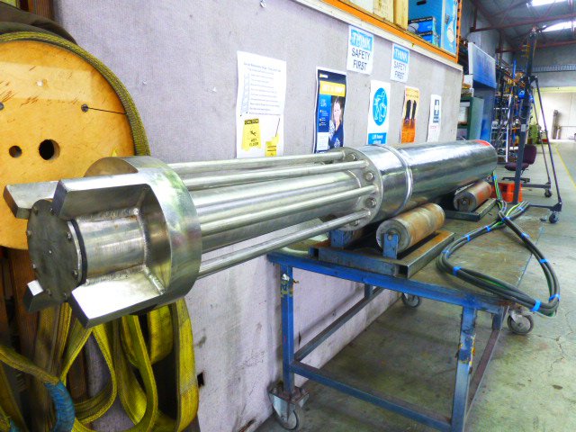
TYPE OF MOTOR
Standard Water Filled
Submersible, water tight, and water filled, with double insulated wire and capable of continuous operation at nameplate power under water in a maximum water temperature of 35 Deg.C. without de-rating, and suitable for “Direct on Line” starting. Six lead motors for “Star/Delta” starting are available as an option.
Heat Exchanger Water Filled
Submersible, water tight, and water filled, with double insulated wire and capable of continuous operation at nameplate power under water in a maximum water temperature of 55 Deg.C. without de-rating, and suitable for “Direct on Line” starting. Six lead motors for “Star/Delta” starting are available as an option. This motor is recommended for high ambient water temperatures and for extended motor life due to the reduced winding temperatures.
Oil Filled.
Submersible, water tight, and oil filled, with double insulated wire and capable of continuous operation at nameplate power under water in a maximum water temperature of 30 Deg.C. without de-rating, and suitable for “Direct on Line” starting. This motor is recommended for very cold water where there is a probability that the water (in a water filled motor) might freeze.
MOTOR RATING
All motors are rated for continuous duty (S1) at nominated voltage and frequency.
WATER COOLING
Cooling water flow rate must exceed 0.5 feet/sec or 0.15 metres/sec. The maximum flow rate must not exceed 10 feet/sec or 2.5 rri/sec. The pH level should be between 6.5 and 8.0.
WATER FILLED
The motors are filled with 90% water and 10% propylene-glycol as standard, but some cold weather markets require 70/30 or even 50/50 ratios to prevent the water from freezing. Clean tap water is the preferred water type. (Oil filled motors are filled with a food grade oil).
MATERIALS
Standard motors have epoxy painted cast iron ends with a 316 Stainless Steel stator frame and 316 hardware. For aggressive water all external metal components are 316 Stainless Steel. (Duplex, Super Duplex and Ni Al Bronze motors can also be supplied).
PRESSURE COMPENSATION
Pressure compensation is managed by using a suitably sized Neoprene bellows to allow for expansion of the internal water as it heats up – or – from external pressure due to the depth of submergence.
SEALS
All motors are fitted with a mechanical seal on the drive end and a stainless steel slinger to prevent external water and foreign material from entering the motor. The seal faces are Silicon Carbide / Silicon Carbide. Some motors can be supplied with double mechanical seals – on request.
BEARINGS
Hydrodynamic carbon sleeve bearings are fitted at both ends of the motor. They are water lubricated, with a large surface area to
give extra support and prevent whipping.
DOWN THRUST BEARING
All the Down-Thrust bearings are Kingsbury style, with hardened and lapped cast stainless steel pivot shoes and a wear resistance carbon/antimony carbon disc.
UPTHRUST BEARING
Up-Thrust bearings are carbon, or, cloth and resin based wear material.
BALANCING
Rotors are balanced to less than 1mm/sec in all planes when measured on No Load.
LAMINATION STEEL
All motors use low loss cold rolled silicon lamination steel with a core loss of 3 Watts/kg at 50 Hz and 1.5T.
WINDING WIRE
Standard winding wire is PEI2 Copper with a continuous watertight polypropylene covering and nylon overcoat for additional mechanical protection.
Testing
All motors are Type Tested and Test Reports can be supplied for individual motors to customer requirements. Temperature rise tests must be conducted while the motor is immersed and subjected to a continuous stream of cooling water – usually as part of a pump test. The temperatures inside the motor, and of the cooling water, are monitored and recorded.
WINDINGS
After the stator leads have been fitted the whole stator is submerged in water and pressurised to 30 psi for 30 minutes and then Hi-Pot tested at 2,500 Volts (for 415V and 460V motors while still at 30-psi pressure. The results are recorded. Please note – this is a “one of” factory test. Future Hi-Pot tests should be done at reduced voltages.
COMPLETE MOTOR
The winding of the complete motor after filling with water/glycol is “Meggered”, (Insulation Resistance Test), and the resistance at 3000 volts, (for 415V motors), should exceed 1000 M0hm. Please note – this is a “one off factory test. Future “Megger” tests should at 1,000 or 500 Volts.
NO LOAD
The complete motor is run on No Load and the No Load currents, No Load voltages, and the “Run down time“ are recorded. The vibration levels are also measured at both ends of the motor and in both planes.
FULL LOAD TEST
All motors can be Full Load Performance Tested for Efficiency, Power Factor, Speed, and Temperature Rise. All calculations are in accordance with IEC Standards. In addition 4 PTl00s are fitted and monitored inside the motor during testing – one in the proximity of the thrust bearing, one in the centre of the stator pack in a stator slot, and one each on the end winding on the drive end and non drive end.
LOCKED ROTOR TEST
All motors can be locked rotor tested to determine the locked rotor current and the locked rotor torque. This test may be done on reduced voltage and a number of points plotted to extrapolate the full load condition.
MECHANICAL TESTS
The runout for the shaft and the flange spigot are measured and recorded. The dimensions of the shat, flange spigot, shaft projection, thrust clearance, and shaft deflection, should also measured and recorded.

